2D points 3D Objects 3D Points Boundary Cursor position Data for selected object Domain Expansion Field Field components Field formula Field tubes Function Generate expansions along 2D boundary Generate expansions for 3D objects Grid formula Grid transformation Info and movie directives Insert Integral Modify 2D expansions MMP Movie Open GL window PET basis PFD (predefined FD) Project Space, plane, arrow, or point Tools and draw Transformation data Window
This dialog is opened when you press the
![]()

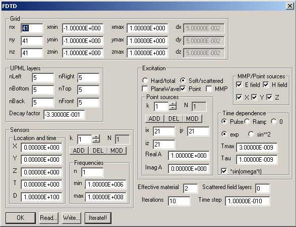
The FDTD dialog allows you to specify the predefined finite difference (PFD) solvers and especially the corresponding FDTD solvers. Beside the number of Iterations and the Time step you need to specify the PFD Grid - which may differ from the grid defined in the Field dialog for the graphic field representataion. The PFD grid is always regular. When the PFD and Field grids do not coincide, OpenMaXwell will apply interpolation routines for computing the field on the Field grid from the PFD data. You specify the PFD grid in the Grid section.
In the UPML layers section you specify the number of UPML layers along the different borders of the PFD grid space. When the number of layers is 0 / -1 / -2, PEC / PMC / Periodic boundary conditions will be assumed on the corresponding boundary. In the current implementation only the simple "hypercube" type of periodic boundaries is assumed, i.e., the periodic symmetry data in the Project dialog is ignored. The Decay factor affects the UPML performance. the default value -.33 should be OK in most cases.
In the Sensors section, you specify one or more PFD sensors. These sensor locations (X, Y, Z) are not necessarily on the PFD grid. OpenMaXwell will interpolate. Each sensor is turned on at time T and remains active during D seconds. OpenMaXwell performs Fourier transforms for the sensor values with frequency points defined in the Frequency section. Note that identical frequency points are used for all sensors.
In the Excitation section you specify the Source type and additional source data. You may add, delete, and modify one or several point sources.
The PlaneWave source is always assumed to propagate in X direction. for 3D PFD and 2D PFD E polarization (specify in the Project dialog!), the E field of the plane wave points in z direction and the H field in y direction. For 2D PFD H polarization (specify in the Project dialog!), the H field of the plane wave points in z direction and the E field in y direction. You may select total or scattered field formulation when a plane wave source is used.
The MMP source is defined as last expansion in the Expansion dialog for a certain domain. OpenMaXwell then imposes the components of this expansion selected in the MMP/Point sources section in all points of the PFD grid within the domain of the expansion either as soft or hard sources.
The third source type is point source. One or several point sources are impressed either as soft or hard sources in a certain points of the PFD grid, specified in the Point sources section. Here PFD grid coordinates are used. Note that the PFD grid starts with number 1, i.e., ix ranges from 1 to nx, etc.
The Time dependence is defined in the corresponding section and in the Project dialog. The function shape defined in the Time dependence section as an envelope function that is multiplied with a sinusoidal function with the Frequency specified in the Project dialog.
The Time-harmonic flag in the Project dialog affects the field that is shown in the Gaphic window. If it is set, the Original field is complex. Its values are then computed from the PFD field using Fourier transform for the frequency specified in the Project dialog and interpolation. When the Time-harmonic flag is turned off, the Original field is real. In this case, interpolation but no Fourier tranform is applied.
Responsible for this web page: Ch. Hafner, Computational Optics Group, IEF, ETH, 8092 Zurich, Switzerland
Last update
17.02.2014