2D points 3D Objects 3D Points Boundary Cursor position Data for selected object Domain Expansion Field Field components Field formula Field tubes Function Generate expansions along 2D boundary Generate expansions for 3D objects Grid formula Grid transformation Info and movie directives Insert Integral Modify 2D expansions MMP Movie Open GL window PET basis PFD (predefined FD) Project Space, plane, arrow, or point Tools and draw Transformation data Window
Select
3D Objects…
from the
Tools menu or press the ![]() button
in the
Tools and draw menu to open this dialog. It
allows you to define how OpenMaXwell shall generate 3D objects from a set of 2D
boundaries and 2D multipoles. Moreover, you can define parameters for the
graphic representation of 3D objects in the
Graphic representation
group of this dialog.
button
in the
Tools and draw menu to open this dialog. It
allows you to define how OpenMaXwell shall generate 3D objects from a set of 2D
boundaries and 2D multipoles. Moreover, you can define parameters for the
graphic representation of 3D objects in the
Graphic representation
group of this dialog.
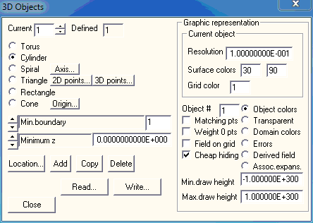
The 3D Objects dialog displays the data of 3D objects and allows you to edit or modify this data. Currently, all 3D objects require the definition of 2D boundaries or 2D expansions. Only some data of these 2D objects may be required for the construction of a 3D object. The corresponding 2D objects will not be used for the 3D MMP modeling. Moreover, one and the same 2D object may be used for the construction of several 3D objects. The most important 3D objects are generated by analytic transformations that correspond to the type of the 3D object. The following transformations have been implemented:
Torus: Rotation around the y axis of the global coordinate system.
Cylinder: Translation along the z axis of the global coordinate system.
Spiral: Transformation consisting of A) rotation around the given axis, B) translation along the given axis and C) translation perpendicular to the given axis. To specify the axis required by these transformations, press the Axis… button.
In addition to that, you may select two simple types of 3D objects that require no definition of a transformation, namely:
Triangle: A triangle with corners A, B, C in 3D space. The coordinates of the corners may be specified in the 3D points dialog that pops up when you press the 3D points… button. Sometimes, it is more convenient to define the corners in the xy plane and to define its position in 3D space as for arbitrary 3D objects (see Location… button below). The 2D coordinates of the corners in the xy plane may be specified in the 2D points dialog that pops up when you press the 2D points… button.
Rectangle: A rectangle with side length a and b. For the default location (see Location… button below), the rectangle will be in the xy plane and its corners will be at (0,0,0), (a,0,0), (a,b,0), (0,b,0). The side length a and b are defined in the boxes below the boxes where you select the 3D object type.
Cone: Move towards the origin (a point in 3D space that is specified when you click the Origin... button).
Additional data for the 3D object is defined in the boxes below the boxes where you select the 3D object type. You must specify the following integer data:
Torus, Cylinder, Spiral, Cone: a) The 2D boundary or 2D expansion numbers used for generating 3D objects are specified in the Min.boundary, Max.boundary, Min.expansion, Max.expansion boxes. Note that you can use more that one 2D boundary or more than one 2D expansion for defining a 3D object, but these boundaries and expansions must have successive numbers because you only can specify minimum and maximum numbers. During 3D MMP computations, the 2D boundaries and 2D expansions used for generating 3D objects will be ignored. Important note: All 2D expansions belonging to a 3D object should be 2D multipoles. b) The Max.multipoles box specifies how many multipoles shall be generated for the 3D object. OpenMaXwell can either generate a discrete set of standard 3D multipole expansions for each 2D multipole expansion that belongs to a 3D object or it can generate a single distributed multipole for each 2D multipole. In the Max.multipoles box you may enter the number of standard multipoles that shall be generated for each 2D multipole. These multipoles will be placed on a curved line along the boundary of the 3D object. When you enter a negative number –N in the Max.multipoles box, up to N multipoles will be generated. In this case, less the N multipoles may be created when the corresponding 2D multipole is sufficiently far away from the boundary. If some of the 2D multipoles that belong to the object are close to the boundary and others are further away, it is strongly recommended to define a negative number –N in the Max.multipoles box. In most cases, it is reasonable to generate distributed multipole expansions. For obtaining such expansions, enter 0 in the Max.multipoles box. The appropriate distributed expansions for a torus, cylinder, and spiral are 3D ring multipole , 3D line multipole, and 3D spiral multipole respectively. Distributed multipoles have a singularity along a curved line. They consist of a superposition of infinitely many 3D standard multipoles placed on the curved line. Since an accurate numeric integration of the 3D standard multipoles would be time-consuming, distributed multipoles are approximated by a discrete set of 3D standard multipoles that are uniformly distribute along the curved line. Note that the data for generating 3D expansions contained in the 3D Objects dialog are used when you decide to generate the 3D multipole expansions for a 3D object. For doing this, press the 3D object… button in the Expansion dialog and press the Generate !! button in the dialog that will pop up. Instead of this, you can also run the movie command GENerate 3DExpansions. For more information, see Expansion dialog and the description of the GENerate command.
Triangle, Rectangle: a) OpenMaXwell generates a set of 3D matching points on the triangle or rectangle. For these matching points, the domain numbers on both sides and other data such as the boundary conditions to be imposed are required. Instead of providing the information directly in the 3D Objects dialog, you must define it in the Boundary dialog. The corresponding 2D boundary may be used for defining several 3D objects. In the Use data of boundary box you specify the number of this boundary. Note that this may be a dummy boundary that does not affect the MMP computation. b) OpenMaXwell can generate multipole expansions for the Triangle or Rectangle. In the Max. multipoles per side box you specify how many multipoles OpenMaXwell shall try to generate on each side of the 3D object and in the Max. multipole order and degree box you specify the maximum order and degree of these multipoles. Note that OpenMaXwell will reduce the maximum order and degree to a reasonable number when not enough matching points are present on the 3D object. Moreover, OpenMaXwell can even entirely delete a multipole when not enough matching points are present on the 3D object. For a Rectangle, OpenMaXwell can generate line multipoles instead of discrete multipoles. To obtain line multipoles, set the negative number of line multipoles in the Max. multipoles per side box. Note that the data for generating 3D expansions contained in the 3D Objects dialog are used when you decide to generate the 3D multipole expansions for a 3D object. For doing this, press the 3D object… button in the Expansion dialog and press the Generate !! button in the dialog that will pop up. Instead of this, you can also run the movie command GENerate 3DExpansions. For more information, see Expansion dialog and the description of the GENerate command.
In addition to the integer data, you must specify the following real data for each 3D object:
Torus: a) Minimum angle (in degrees) b) Sector angle (in degrees) for the rotation, and c) the aspect ratio of the matching points that will be generated on the 3D surface: Mat.Pt. aspect ratio box. For obtaining standard matching points with a square area, set the aspect ratio AR equal to 1. For AR>0, different from 1, the matching points obtain a rectangular area with "side length along the transformation line" = "side length perpendicular to the transformation line" / AR. For AR<0, the number of matching points along the transformation line is fixed and equal to -AR.
Cylinder: a) Minimum z value, i.e., minimum translation along the axis, b) Length of the cylinder, and c) the aspect ratio of the matching points that will be generated on the 3D surface: Mat.Pt. aspect ratio box. For obtaining standard matching points with a square area, set the aspect ratio AR equal to 1. For AR>0, different from 1, the matching points obtain a rectangular area with "side length along the transformation line" = "side length perpendicular to the transformation line" / AR. For AR<0, the number of matching points along the transformation line is fixed and equal to -AR.
Spiral: a) Delta r, i.e., size of the radial translation perpendicular to the axis, b) Delta phi, i.e., sector angle of the rotation, and c) Delta z, i.e., length of the translation along the axis, d) the aspect ratio of the matching points that will be generated on the 3D surface: Mat.Pt. aspect ratio box. For obtaining standard matching points with a square area, set the aspect ratio AR equal to 1. For AR>0, different from 1, the matching points obtain a rectangular area with "side length along the transformation line" = "side length perpendicular to the transformation line" / AR. For AR<0, the number of matching points along the transformation line is fixed and equal to -AR.
Triangle: a) Match.pt.side length, i.e., the length of the sides of the matching points generated on the triangle, b) Multipole density, c) Multipole distance. Note that OpenMaXwell can automatically generate a set of one or several multipoles for the triangle. The parameters Multipole density and Multipole distance affect the placement of the multipoles. By default, these parameters should be equal to 1. When you increase the Multipole density, the distances between the multipoles will be reduced. When you increase the Multipole distance, the distances of the multipoles from the triangle will be increased.
Rectangle: a) X side length, i.e., the side a of the rectangle, b) Y side length, i.e., the side b of the rectangle, c) Match.pt.side length, i.e., the length of the sides of the matching points generated on the triangle, d) Multipole density, e) Multipole distance. Note that OpenMaXwell can automatically generate a set of one or several multipoles for the triangle. The parameters Multipole density and Multipole distance affect the placement of the multipoles. By default, these parameters should be equal to 1. When you increase the Multipole density, the distances between the multipoles will be reduced. When you increase the Multipole distance, the distances of the multipoles from the triangle will be increased.
Cone: a) Minimum z value, i.e., z component of the minimum translation towards to origin, b) Delta z, i.e., height of the cone, c) Multipole distance, i.e., a distance factor cor setting 3D multipoles along a line from the original 2D multipole (defined at z=0) to the origin of the cone (this factor should be between 0 and 1), and d) the aspect ratio of the matching points that will be generated on the 3D surface: Mat.Pt. aspect ratio box. For obtaining standard matching points with a square area, set the aspect ratio AR equal to 1. For AR>0, different from 1, the matching points obtain a rectangular area with "side length along the transformation line" = "side length perpendicular to the transformation line" / AR. For AR<0, the number of matching points along the transformation line is fixed and equal to -AR.
Note that only one 3D object’s data can be displayed and edited at a time. To select an object, specify it’s identifier in the Current box. The total number of existing 3D objects is given in the Defined box.
When a 3D object is generated by a transformation acting on 2D boundaries and 2D expansions that are within the xy plane, its location and orientation in 3D space is often not the desired location and orientation. Therefore, you might wish to move or rotate the 3D object to another position in 3D space. OpenMaXwell associates a local coordinate system to each 3D object that allows you to put each 3D object anywhere in space. The local coordinate system is defined in the dialog that pops up when you press the Location… button. The original location of a 3D Object is the following: Origin at (0,0,0), X direction vector (1,0,0), Y direction vector (0,1,0), and Z direction vector (0,0,1).
Assume that you have a 2D boundary that is a circle of radius R around the origin in the xy plane. When you set the Axis… equal to the z axis (Origin (0,0,0), X direction (0,0,1)) and generate a 3D cylinder with Minimum z = 0 and Length = L with this 2D boundary, you obtain a circular cylinder of radius R that stands on the xy plane and has an axis in z direction through the origin (0,0,0) of the original coordinate system. When you want to move this cylinder along the vector (xm,ym,zm), you simply press the Location… button and specify the Origin at (xm,ym,zm) in the Space, plane, arrow, or point dialog that pops up. When you want to rotate the cylinder, you can either specify the X direction and Y direction vectors in the Space, plane, arrow, or point dialog or you can use the buttons in this dialog for performing rotations around the X, Y, or Z axis.
To add a 3D object, specify its data and press the Add button.
To copy a 3D object, select the object to be copied in the Actual box and press the Copy button. Since it makes no sense to define two identical 3D objects, you should modify the data of the copied object afterwards.
To delete a 3D object, select it in the Actual box and press the Delete button. Note that at least one 3D object must be present.
The Graphic representation group contains data that specify how the 3D objects will be represented either in the standard graphic windows or in the OpenGL window.
The data with in the subgroup Current object will affect only the representation of the 3D object specified in the Current box. This allows you to use different colors and resolutions of the grids for different objects.
First of all, each object may either be represented by the matching points used for the MMP computation or be grid lines along its surface. The former representation is used when the Matching pts box is checked. This representation is useful to verify if a reasonable set of matching points has been generated and to display the errors in the matching points, but it is less nice and less flexible than the grid representation. Especially when there are many matching points, the matching point representation might be time consuming and this is not desirable as long as you are modeling. Therefore, it is preferable to start with relatively rough grid representations. Note that the distances between neighbor grid lines are specified in the Resolution box, i.e., high resolution is obtained when a low value is set in this box. For example, when the object is a circular cylinder of radius R=1 and length 2, you might set Resolution = 1 for a very rough representation with 3 grid lines along the axis of the cylinder and 7 grid lines along the circle. If you set Resolution = 0.1, you will obtain approximately 10 times as many grid lines in both directions, i.e., approximately 100 times as many grid cells. Since the memory requirement and computation time is more or less proportional to the number of grid cells, it is important to set an appropriate number in the Resolution box for each 3D object. Note that OpenMaXwell limits the number of grid lines in each direction in order to avoid excessive computation time when a too small number is specified in the Resolution box.
OpenMaXwell can either draw all existing 3D objects or only the object specified in the Object # box. To draw all 3D objects select 0 in the Object # box. You can also let OpenMaXwell draw the first N objects only when you select –N in the Object # box.
The grid for the field visualization defined in the Field dialog may be considered as a special 3D object that is not explicitly defined in the 3D Objects dialog. When the Field on grid box is checked, the derived field specified in the Field dialog is drawn together with the 3D objects. This is important to obtain proper hiding. Currently, two different hiding procedures are implemented for standard graphics windows. To select the hiding procedure that is faster but less reliable, check the Cheap hiding box. Moreover, OpenGL provides its own hiding procedure. Note that different field representations were implemented for the different hiding procedures. Especially the shape of arrows and the colors that represent the strengths of the represented field depend on the hiding procedure.
The drawing of 3D objects may be restricted to an area around the xy plane. Only those parts that have z’ coordinates between Min. draw height and Max. draw height will be drawn, where z’ is perpendicular to the view plane specified in the Field dialog. By default, Min. draw height is very small and Max. draw height is very big. This makes sure that all parts of the 3D objects are drawn.
3D objects are either represented by a set of matching points or by a set of grid cells. Each matching point and each grid cell consists of a bordered quadrangle. The quadrangle has two sides. You may associate two different colors to the sides in the Surface colors boxes. These colors are only used when the Object colors representation is selected.
In addition to the surface colors, you may associate a color to the borders of the quadrangles in the Grid color box.
Since parts of a 3D object may be hidden between other parts of the 3D objects, you may wish to suppress the drawing of the surfaces of the quadrangles. Select the Transparent representation for this purpose. Note that transparent drawing is quickest.
Note that the surface of a 3D object separates two domains with different material properties and different domain numbers. The domain numbers of both sides of the quadrangles that represent the surface are computed automatically from the 2D boundaries that are used for generating the 3D object. To check whether the correct domain numbers have been associated with the object, make sure in the Domain dialog that each domain has a unique color and select the Domain colors representation.
To analyze the results of a 3D MMP computation, it is reasonable to evaluate the errors along the boundaries. Select Errors representation for a graphic visualization of the errors on the surface of an object. Note that OpenMaXwell can evaluate the errors not only in the matching points, but also anywhere on the surface of an object. This is especially important when the overdetermination of the MMP matrix is not sufficient. This may lead to inaccurate results with relatively small errors in the matching points but considerably higher errors anywhere else. Try different Resolution values and compare the resulting error representations! Note that the error representation may be slow when many quadrangles are present, because the errors need to be computed for every quadrangle before it is drawn.
Instead of the errors, OpenMaXwell can also compute and represent the derived field defined in the Field dialog for each quadrangle when the Derived field representation is selected. Note that this representation may be slow when many quadrangles are present, because the derived field needs to be computed for every quadrangle before it is drawn. However, this representation may be very useful, because it allows you to inspect the field on the surface of any 3D object. Note that you may define dummy 3D objects that are not used for the 3D MMP computation. You can take advantage of dummy 3D objects for representing the field on curved surfaces.
In 3D models, 3D multipole setting may be cumbersome. You may wish to check how many multipoles are associated to each matching points. For a visualization, select Assoc. expans. and check the Matching pts box. The color number of each matching point then indicates how many expansions are associated (0: white, 1: black, 2: red, 3: green...). In a good model 1 or two expansions should be associated to each matching point - provided that no expansions other than 3D multipoles are applied. Currently, only 3D multipoles are being checked. This feature is under construction.
Press the Read… button to read 3D object data from a file. A file name dialog will allow you to select any file name to read from. Note that you can either overwrite all 3D objects with the 3D objects defined in the file, or you can insert the 3D objects in the file along with the existing 3D objects. The Insert dialog will prompt you to specify which option you prefer.
Press the Write… button to write 3D object data to a file. A file name dialog will allow you to select any file name to write to.
Press the Close button to close the dialog. Note that the current data in the edit boxes become effective when the dialog is closed.
Responsible for this web page: Ch. Hafner, Computational Optics Group, IEF, ETH, 8092 Zurich, Switzerland
Last update
17.02.2014