PCs waveguide discontinuities

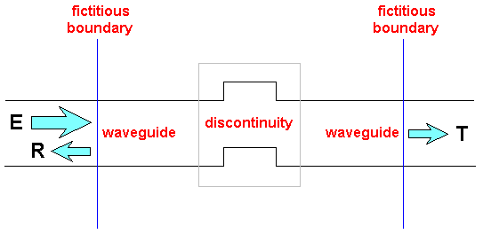
Figure
1: The basic idea of the analysis of waveguide discontinuity is presented. The
"defect" of waveguide structure is isolated by two
(or more) fictitious boundaries which will be used for field matching between
our discontinuity structure and the eigenfields
of connected waveguides. A reflection and transmission properties of the
waveguide discontinuity are characterized by
the transmission (T) and reflection coefficients (R) (which can be defined by means of
the field amplitude or by means of the field power
for unit excitation (E)).

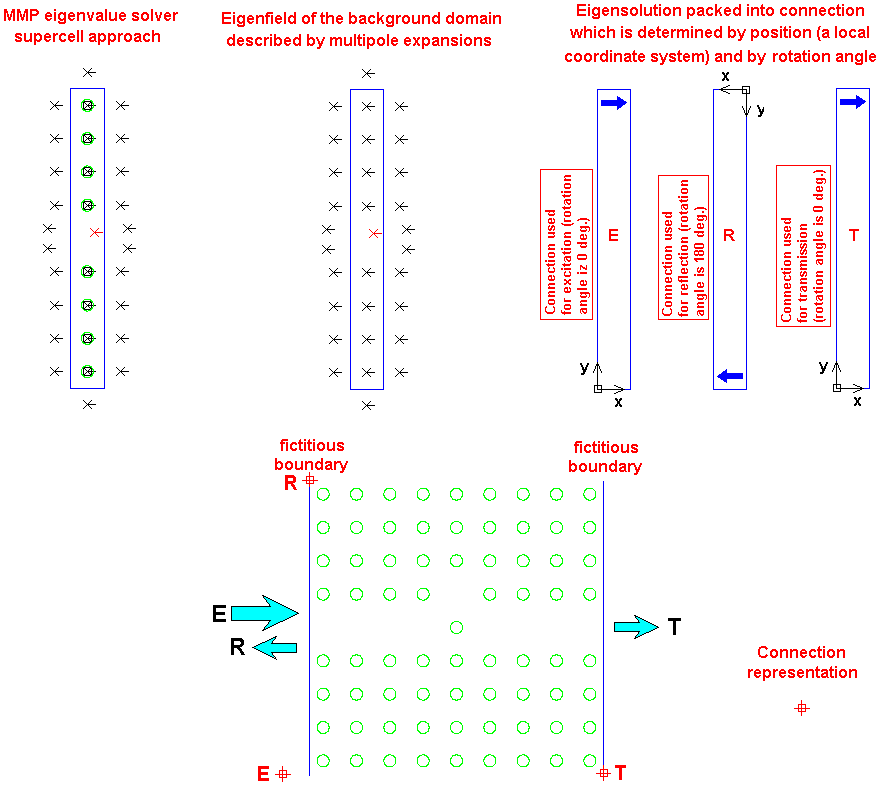
Figure
2: The connection concept for a waveguide discontinuity analysis using MMP is
described. At the beginning, the MMP
eigenvalue solver is used for eigenfield determination of PCs line defect
waveguide at certain frequency. Having a such eigenfield
we are able to pack and store this information by using corresponding multipolar
expansions. This expansions package is called
"connection". The waveguide discontinuity is introduced by a simple
displacement of a single dielectric rod. At a given frequency
it is necessary to compute eigensolution of the infinitely long waveguide. Based
on this solution we will define three different
connections with an appropriate positions and rotational angles in order to have
a correct representation of the input, reflected,
and transmitted electromagnetic power. As a result of field metching along the
fictitous boundaries, using MMP apprach,
we are able to compute unknown complex amplitudes for a corresponding
connections, i.e. corresponding reflection (R) and
transmission (T) coefficients in the case of unit
excitation (E).


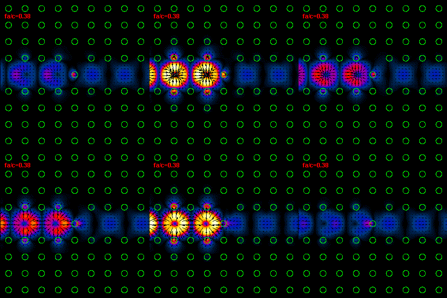
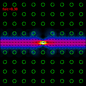
Figure
3: The infrared light propagation along the PCs waveguide defect structure (left
hand side) and the time average Poynting vector
(right hand side) are presented. As one can see, our simple discontinuity in
waveguide structure produces a very large reflection, R=82%,
and low transmission, T=18% (R and T are defined by means of power). The most
important question of this connection approach
for the waveguide discontinuity analysis is how far from discontinuity our
fictitious boundaries should be placed. The distance between
the discontinuity and the termination must be large enough in order to prevent
that the evanescent field (produced by discontinuity) reach a port,
i.e. fictitious boundary. Otherwise, this evanescent field will produce
a significant field mismatching along the termination boundary, because of the
fact that
our connections consist only eigenfield informations. According to the analysis
performed by Esteban
Moreno this distance should be at least one effective wavelength of our line defect waveguide at
corresponding frequency. This effective wavelength
can be easily found by using dispersive relation of the line defect waveguide.