PCs antenna (free space termination at optical frequencies)

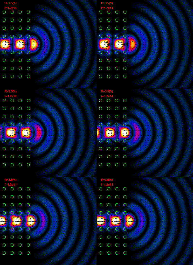
Figure
1: The light emission at the end of the PCs waveguide (free space termination of
PCs waveguide),
the x0y plane component of Poynting vector is plotted.

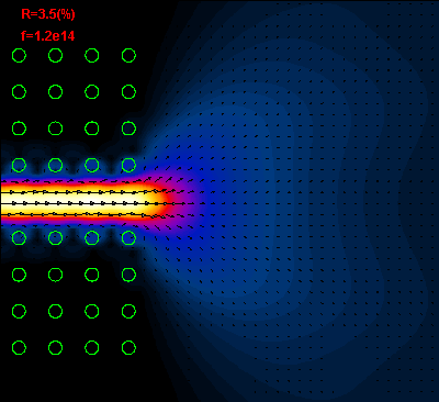
Figure 2: The time average Poynting vector field is plotted.

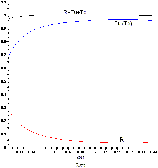
Figure
3: The frequency characteristic of PCs antenna. It is possible to see that
presented
free space termination of PCs waveguide
at wide frequency range has a very low reflection (compared with the microwave
waveguides, for example).